
Remember me
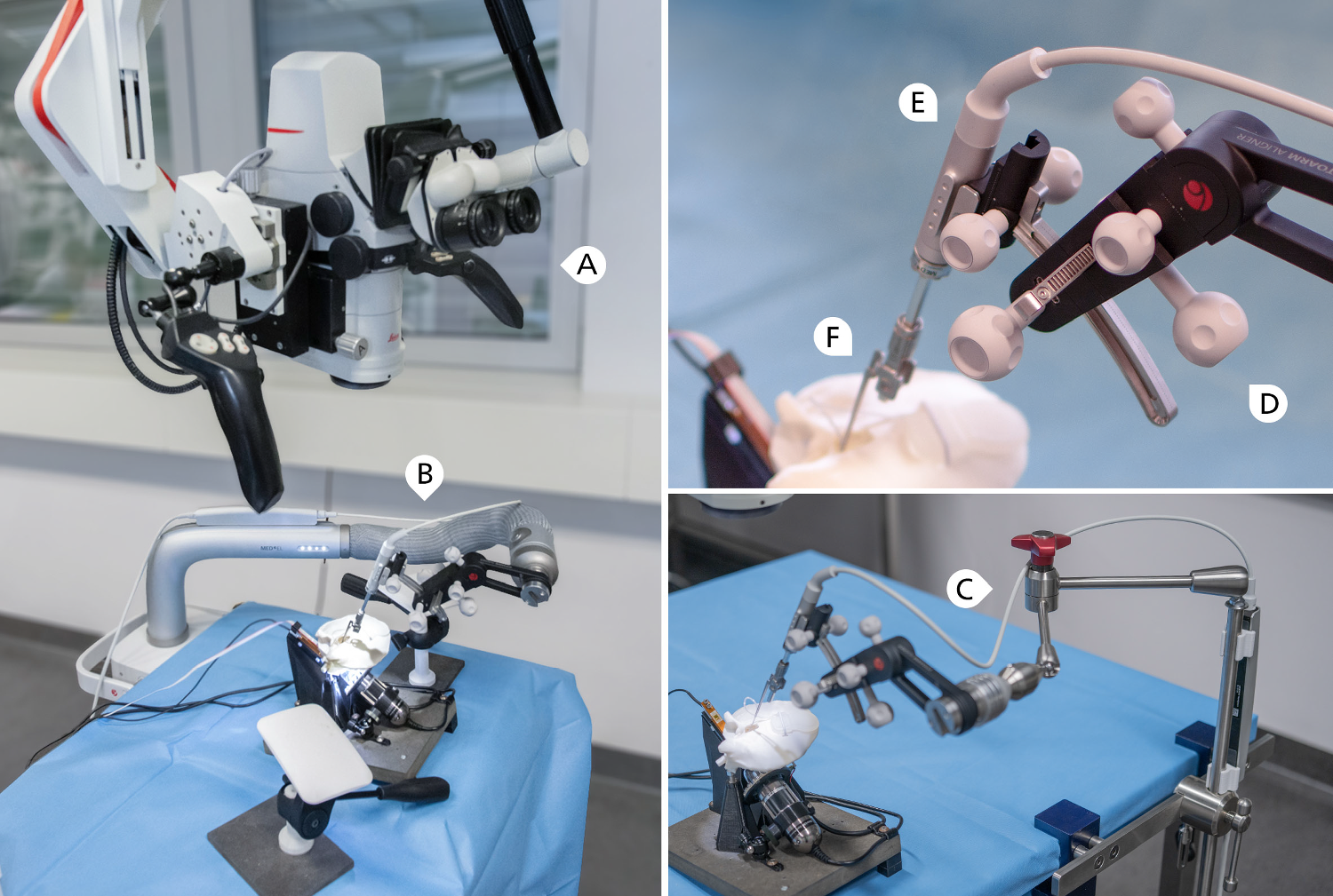


The setup is comprised of four main parts which include (A) a positioning arm, (B) an alignment unit (OTOARM Aligner), (C) a linear actuator (OTODRIVE Handpiece) operated by a laptop computer and foot pedal and (D) a self-closing forceps (Forceps OD). Figure 1 shows the complete setup and a close up of the actuator end. Each component is described in detail below.
Fig. 1
Left: Experimental setup with surgical microscope (A) and the robot-assisted insertion device mounted to a positioning arm (B). Lower right: Due to limited availability the positioning arm was replaced with a medical articulated arm (C) for 22 insertions. Hand rests that simulate patient extent are removed in this photograph for better visual overview. Upper right: Close-up of the assessed device, consisting of OTOARM Aligner (D) with the OTODRIVE Handpiece (E) mounted and forceps OD (F) partially extended into the temporal bone model Manual procedures were conducted in the same setup with the positioning arm and insertion device removed
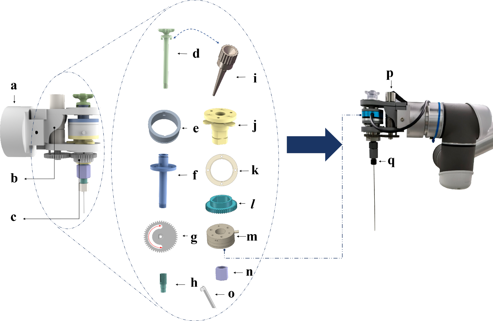
OTODRIVEOTODRIVE handpiece features a metal shaft with an internal magnetic core that moves along the shaft, magnetically coupling with the forceps, allowing for a total travel of 40 mm. The OTODRIVE handpiece is connected to the OTODRIVE box, which serves as the control unit and offers Blutooth or Ethernet connection to a computer running the OTODRIVE software. The software allows adjustment of the feed rate in ten uniform steps from 0.1 mm/s to 1 mm/s and visualizes the current actuator position. It also permits setting a relative zero position, shown alongside the current absolute position. The OTODRIVE foot pedal, equipped with forward and backward switches, also connects to the OTODRIVE box by which the user activates the motion and its direction. The OTODRIVE handpiece includes an interface to be attached to the OTOARM Aligner.
Positioning armAn electro-mechanical, table mounted positioning arm was used for a subset of the robot-assisted insertion experiments. The arm is attached to the contralateral side railing of the operating table. It reaches superiorly around the patient’s head, up to a position posterior to the surgical site. Activating a button on the distal end transitions the arm into a flexible configuration, allowing to reposition the acutator. After initial placement, the device position can be fine-tuned with OTOARM Aligner. It features manually operated knobs for adjustments across three linear axes: inferior to superior (10 mm range), anterior to posterior (10 mm range), and along the actuator axis (26 mm range). It allows adjustments along two rotational axes to determine the medio-lateral and basoapical insertion angles (20\(^\) range).
Due to limited availability of the electro-mechanical positioning arm for 22 robot-assisted insertions, a FISSO articulated arm (Baitella AG, Zürich, Switzerland) was used for positioning, and the OTOARM Aligner was attached using a customised adaptor.
Study protocolSixty insertion experiments were conducted by three expert cochlear implant surgeons. Every surgeon executed 10 insertions using robotic assistance and 10 following the standard manual protocol. We alternated between manual and robot-assisted procedures for each insertion, to minimize the influence of electrode degradation.
The procedure for each experiment encompassed the entire implant placement process: electrode array insertion, positioning muscle tissue around the round window and into the facial recess, and coiling the electrode cable into the mastoid cavity. The steps were performed under a surgical microscope, with conventional surgical tools available. For robot-assisted insertions, additional steps included the initial placement and alignment of the device, fixation of the electrode, and instrument removal. For all manual tasks, including those performed after robotic assistance, surgeons were instructed to adhere to established soft surgery principles.
Before the expirements were started, each surgeon received an introduction to the robotic system’s operating components. Surgeons were permitted to familiarize with the tool within the in-vitro model until they felt proficient to proceed with the insertion experiments. For robot-assisted insertions, the feed-forward speed was set to 0.3 mm, which is a frequently used value [8, 10].
The measurements were conducted in two sessions per surgeon, with two new electrodes prepared for each session. Electrodes were replaced after six insertions. Three electrodes were replaced due to detected defects, for which three previously used electrodes were reutilized.
Experimental setupWe used a validated in-vitro model within a realistic surgical environment. The setup includes a scala tympani model housed in a temporal bone model, derived from microtomography scans of human temporal bones. Access to the round window is through a standard mastoidectomy and posterior tympanotomy. The scala tympani model was fabricated by casting an ABS preform into clear epoxy resin and dissolving the preform post-curing, allowing for accurate reproduction of the 3D macro-anatomy without layer artifacts typical of 3D printing. Model and electrodes were coated with a hydrophilic polymer brush (graft copolymer with a poly(L-lysine) backbone and poly(ethylene glycol) side chains, PEG-g-PLL) to simulate realistic friction conditions. Details of the fabrication process and validation are discussed in a technical note [11].
To measure insertion forces, the temporal bone and scala tympani models are mechanically decoupled. The scala tympani is mounted to a load cell (KD78, ME Meßsysteme GmbH, Hennigsdorf, Germany), aligned with the long axis of the cochlea. The apex connects to a pressure sensor (MS5837-02BA, Measurement Specialities, Inc, Hampton, VA, USA). The model is oriented according to our standard clinical protocol, in the lateral position with the head hyperextended. The setup has been extensively described and utilized in previous studies [4, 9, 12].
Twelve MED-EL Flex28 electrode arrays (MED-EL GmbH, Innsbruck, Austria) were used, and connected to a dummy implant housing. Damaged arrays were replaced. A thin, flexible film (stretched Parafilm "M" laboratory film, Bemis Company, Inc, Neenah, WI, USA) with a hole (radius 0.25 mm) was placed at the entrance of the scala tympani model to mimic the round window membrane. This film was replace after each insertion.
The procedures were conducted under a surgical microscope (M525, Leica Microsystems GmbH, Wetzlar, Germany). Surgeons had access to specialized forceps (MED-EL SoftGrip Forceps), a surgical claw (MED-EL Surgical Claw Angled), a pick, and standard forceps. Porcine abdominal tissue was used for the placement of autologous tissue around the round window and within the posterior tympanotomy.
Data processingRaw data from load cell, pressure sensor, microscope image of the scala tympani and surgeon’s view was recorded with a custom python program. We post-processed data in python using the scipy scientific computing library [13]. In order to map the signals to the individual surgical steps, we extracted the corresponding timestamps from the video recording of the surgical microscope.
Force variationForce variation was defined as the time derivative of the insertion force. Mean force variation was defined according to Nguyen et al. as the root mean square of the force variation [14].
Pressure peaksPressure peaks were identified using scipy’s signal.find_peaks. The strength was obtained by the value of the highpass-filtered signal, with a cutoff frequency set at 1 Hz. We classified strong pressure peaks as those exceeding 100 Pa, following the work of Greene et al. [15].
Angular and linear insertion depthWe manually annotated the positions of electrode contacts within the scala tympani model in the microscope recordings at 15-second intervals. These annotations were then tracked over time using the OpenCV library [16] and DaSiamRPN network for visual object tracking [17].
The angular insertion depth was defined as the azimuth coordinate of the uppermost electrode contact in the local cochlear coordinate system according to Verbist et al. [18]. For each video frame we obtained the electrode centerline by constructing a smooth spline approximation which connects the location of the round window and all intracochlear electrode contacts. The linear insertion depth was defined as the length of this electrode centerline.
Insertion speedInsertion speed was defined as the time derivative of the linear insertion depth. For representing the inserton speed distribution, we normalized the data by distance. For this, we multiplied each bin count of the histogram of insertion speeds by its corresponding speed value.
Statistical analysisThe distribution of all measured variables was assessed using the Shapiro-Wilk test for normality. Measurands exhibiting normal distribution are presented as mean ± standard deviation. Measurands not conforming to a normal distribution are reported as median and interquartile range IQR.
Forceps opening forcesForceps opening forces were measured with a spring scale (SAUTER 281-752, Kern & SOHN GmbH, Balingen-Frommern, Germany).
Comments (0)