
Remember me
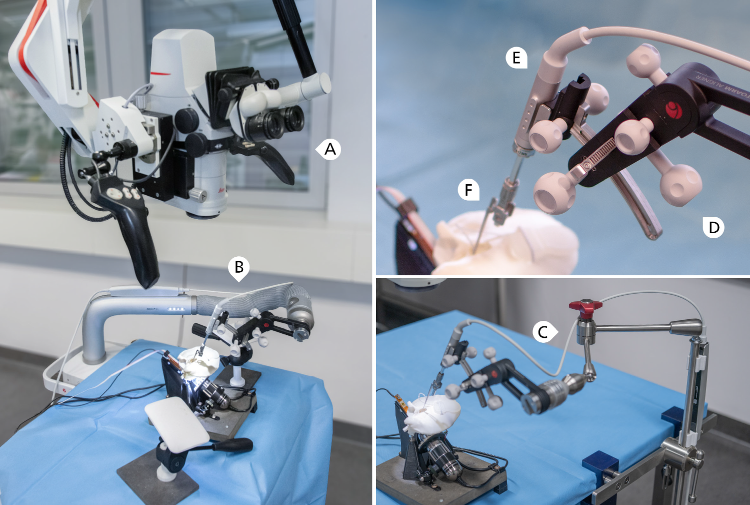
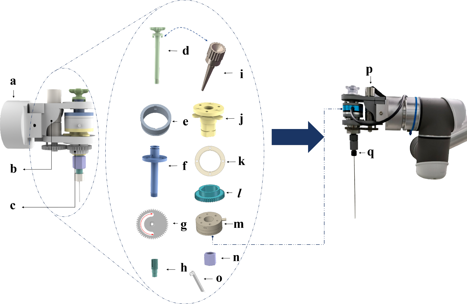


This section presents a description of the principal components of the experimental setup, as illustrated in Fig. 2.
Fig. 2
The experimental setup comprises a Meca500 industrial robot and an optical fiber coupled with a swept-source OCT engine
OCT-based distance sensingThe IOL Master 700 biometry device (ZEISS, Germany), which is equipped with a 2 \(\hbox \) high-speed swept-source laser engine with a center wavelength of 1060 nm, is used as OCT engine. It provides an imaging depth of approximately 60 \(\hbox \) in air and an axial resolution of 30 to 40 \(\upmu \hbox \).
We utilize a custom sample arm fiber (HI-1060, LaseOptics, USA), equipped with a 300 \(\upmu \hbox \) diameter focusing ball lens with 2 \(\hbox \) working distance at the tip. The end of the fiber is stripped and incorporated into a protective stainless steel ferrule with a 760 \(\upmu \hbox \) outer diameter and 15 \(\hbox \) length.
Robotic motion controlThe Meca500 (Mecademic, Canada) is a 6 degrees of freedom (DOF) robotic arm with motion repeatability of 5 \(\upmu \hbox \). Trajectories are robotically executed for repeatability and commands are sent to the robot via robot operating system (ROS).
The iiOCT tip is moved on a parametrized Archimedean spiral. The curve is comparable to the movements observed during core vitrectomy, during which the model is constructed. Consequently, we anticipate that the model construction will exhibit similar behavior when utilizing data derived from actual surgeon movements instead of the spiral scan. The spiral
$$\begin f\theta \mapsto \left( b\, \frac\cos \theta ,b\, \frac\sin \theta , 0\right) \end$$
(7)
commences at the center of the eye and is aligned with the coronal axis. Parameter \(b \in \mathbb \) controls the distance between loops and is set to \(b=0.5\) mm. For 18 revolutions, we set \(\theta \in [0,36\pi ]\). Knowing the length of the spiral, we choose \(\theta \) in such a way that the points on the spiral are equispaced with a distance of 0.1 \(\hbox \) between consecutive points.
Distance sensor calibrationThe optical fiber is attached to a 3D printed mount using a fiber holder to interface with the Meca500 robotic arm. Precise knowledge of the iiOCT pose relative to the robot end effector is essential for reconstructing retinal points from iiOCT measurements. To accurately estimate such a transformation, we adapt the calibration procedure proposed by Sifferman et al. [19]. To comply with the kinematic constraints in vitreoretinal surgery, we impose a remote center of motion (RCM) at the trocar, i.e. the point on the sclera of the eye where the instrument is inserted into the intraocular space.
We measure the distance to a static OCT calibration plate from 250 different robot poses. We then determine the iiOCT pose with a sequential least squares programming (SLSQP) optimization approach using the known pose of the end effector and the condition that all measured points must lie on one plane. Calculations were performed on an Intel Core i5 processor. The calibration yielded an average residual error from the plane of less than 30.03 \(\upmu \hbox \). We also perform a sensitivity analysis to understand how critical the extrinsic sensor calibration is to the sphere fitting, as shown in Fig. 3. The sensor pose is systematically perturbed in the vertical direction and rotated in the image plane.
Fig. 3
a If the sensor pose (green solid line) is calibrated, the true size and position of the estimated sphere can be obtained. b An incorrect sensor pose relative to the robot end effector results in an incorrect size and position (red dashed arc). c The calibrated sensor pose (red dot) yields superior SF results in terms of absolute diameter error when compared to other sensor poses (blue dots)
Table 1 The realistic test eye shapes considered for evaluation of our approachTest eyesSix different eye shapes are constructed as point clouds based on parameters found in the literature (Table 1) and are used in both simulation and real-world testing of the fitting algorithms. The selected eye shapes are intended to represent both common eye geometries, including myopia and hyperopia, as well as pathological conditions such as staphyloma and retinal detachment. A staphyloma is a circumscribed protrusion at the back of the eye. A retinal detachment can occur when the retina breaks and the vitreous leaks into the subretinal space.
The average emmetropic eye is oblate [1]. As myopia increases, eyes become larger in width (0.14 \(\hbox /\textrm\)) and height (0.10 \(\hbox /\textrm\)), but even more so in length (0.30\(\,\hbox /\textrm\)) [2]. Almost half of highly myopic eyes have a pointed shape in the posterior part [20]. Hyperopia, like myopia, is axial in nature [21]. Here, we assume that the relationship between height, width, and length, as previously mentioned, also applies to hyperopia. We assume a visual acuity of −12 diopters for all pathologies because highly myopic patients are considerably more likely to develop retinal detachment, staphyloma, or pointedness.
The lower halves of all six eye shapes in Table 1 are converted to.stl files and 3D printed with Extrudr PLA NX2 filament on an i3 MK3S+ printer (Prusa, Czech Republic). The layer height is 0.05 \(\hbox \). The ex vivo porcine eyes are cut in half (open sky) and placed in a spherical eye holder with an inner diameter of 13 \(\hbox \). The vitreous, which is firmly attached to the optic nerve head, is removed with a scraper (dry).
ExperimentsAs a first evaluation, we test the performance of our modeling approach and transition strategies using the defined eye shapes from Table 1 in a simulation environment (Fig. 4). This strategy enables a quantitative evaluation of the modeling component, as accurate reference geometry is available and independent of inaccuracies arising from sensor, calibration, 3D printing, and registration.
Fig. 4
Simulation environment that simulates iiOCT measurements to reconstruct retinal points based on different robot trajectories (left) and real-world measurement points of a hyperopic eye phantom, along with the corresponding ellipsoid fit (right)
The instrument tip is modeled as a point in space and the instrument is modeled as a straight line connecting the instrument tip and the trocar. The simulated distance measurement calculates the intersection point between the iiOCT beam and the reference retina. To simulate real conditions, we perturbed the simulated distance measurements with a normal distribution with a standard deviation of 20 \(\upmu \hbox \), which is in the range of the axial resolution of our sensor.
For data acquisition in the real world, the six printed eye shapes and three ex vivo porcine eyes are utilized. The RCM is positioned along the visual axis for both the pig and the printed eyes, due to the limited height of the shapes to be scanned. To synchronize the OCT stream with the robot encoder data, a unique robot trajectory is executed in the form of an amplitude modulated sinusoidal signal. The synchronization results in a time deviation between the time series of less than 2.6 \(\hbox \).
Evaluation metricsThe mean absolute error (MAE) serves to quantify the discrepancy between the fitted sphere or ellipsoid and its corresponding ground truth, thereby enabling an assessment of the overall accuracy of the robotic measurement system and the modeling. The measurement mean absolute error (MMAE) represents the deviation of the measurement points from the ground truth shapes, thereby enabling the assessment of the inaccuracies of the measurement setup. It can be regarded as a benchmark that the MAE cannot surpass, irrespective of the quality of the fitting. The fitting mean absolute error (FMAE) represents the deviation of the data points from the fitted shapes, thereby enabling the assessment of the accuracy of the SF and the EF within the scanned region. In contrast, the MAE is evaluated on a global scale.
To calculate the MAE, the MMAE and the FMAE, the model and the ground truth are sampled with \(500 \times 500\) points. In order to account for the fact that the retina does not represent a full ellipsoid due to the presence of the anterior eye segment, the anterior five millimeters in length direction are cropped.
For the evaluation of fitting on the printed shapes, the ground truth geometry of the eye is available, but the absolute position is unknown. Consequently, the fitted point cloud is aligned to the reference using a registration based on iterative closest point (ICP). The implementation from Open3D was used, and the maximum correspondence distance was varied between 0.1 and 1.0. In the absence of a ground truth geometry, we calculated only the FMAE for the porcine eyes.
Comments (0)