
Remember me


Recently, there is increasing interest in unmanned aerial vehicles (UAVs) in a wide variety of fields. Recent investigations and researches are published (Akhloufi et al., 2021) regularly since many years. Using UAVs to detect and monitor fire hazards demonstrates an effective contribution, whether they are controlled remotely or incorporated with intelligent computer vision software (Zhang et al., 2014). Indeed, the autonomous drones are becoming an essential tool in fire and rescue management (Moumgiakmas et al., 2021). Even though many technology advances have been made in relevant designing technologies looking for the maximum of efficiency with popular items still challenging. In fact, a huge advancement is continuously made in (MEMS) Micro-Electro-Mechanical Systems and (NEMS) Nano-Electro-Mechanical Systems technologies allowing manufacturing miniature sensors, actuators and controllers (Burggräf et al., 2019). Autonomous applications have to be built for specific missions. Quadrotors are one of the most popular (Manoj Kumar et al., 2021) and their advantages of hovering capabilities, vertical taking off and landing (VTOL) are applied to fixed wing.
The flight behavior of a quadrotor is impacted by several factors such as the wind, the weight variation, the speed, the trajectory to follow and the evolution of its own internal parameters (e.g., Wei et al., 2023). Due to sophisticated nonlinearity and strong coupling parameters under-actuating an absolutely unstable dynamic model, these phenomena are augmented. Indeed, to control a quadcopter we have four fixed rotors to control its six degrees of freedom in space. Any control strategy for manual, or autonomous missions depends on the reliability of the mathematical model. A valid and accurate mathematical model can be extracted from a commercial or self-designed Quadrotor using identification and laboratory experiments (Tahir et al., 2023).
Research has been conducted on the altitude and attitude control methods for quadrotors in the literature. The control strategy including Sliding Mode Control (SMC) is often used (Rinaldi et al., 2023). It presents good robustness results for nonlinear systems in presence of parameter uncertainties and external disturbances (Manoj Kumar et al., 2021). It has been shown that this technique can be applied in model-free control (Wang et al., 2016) or associated with LQR optimization, adaptive or back-stepping modes (e.g., Bouabdallah and Siegwart, 2005; Li et al., 2014; Ghamry et al., 2016) for indoor and outdoor operations. The augmented SMC controller reduces the disadvantage of the chattering problem. There may be undesirable oscillations in practice, called chattering problems, of finite frequency and amplitude.
For general application, Proportional Derivatives (PD) and Proportional Integrator Derivatives (PID) control techniques continue to be widely used due to their simplicity, real-time implementation and no mathematical model requirement (e.g., He and Zhao, 2014; Nguyen and Hong, 2018). Recently, has proposed a PID approach control for enhancement of a DJI-F450 drone model. They are also associated with other control techniques to improve their efficiency and reduce their disadvantages. To compensate disturbances in attitude and altitude control, a PID and fuzzy – PID controls combination was proposed by Kuantama et al. (2017). Using predictive models and linear quadratic optimisation techniques, PID controllers in discrete version have also been investigated by Khan and Kadri (2015) and Reizenstein (2017). In fact, a PID controller cannot cover all fluctuations in the dynamics of a system. However, it can cover a significant amount of uncertainty and ensure fast control response. This is crucial for aerial quadrotors controlling attitude to avoid obstacles and perform demanding maneuvers in urban or forest areas. PID control has been combined with a variety of tuning approaches in several studies in order to improve its efficiency. Auto-tuning algorithms using metaheuristics deep reinforcement learning, neural network or fuzzy rules are recently explored (e.g., Doukhi et al., 2017; Sheta et al., 2021). Basically, the PD-PID controllers present the advantage of having only two effects (for the PD controller) and three effects (for the PID controller) adjusted with the corresponding parameters. The system behavior could be modified with the forementioned parameters. In the existing literature, many works have been conducted for the evaluation of these parameters without necessarily appealing a mathematical model of the system. The effectiveness of controllers has long been established in the industry. Their utilization in more advanced systems such as robots and drones has also been demonstrated. In fact, their flexibility and simplicity made the PD-PID controllers gain popularity among researchers and practitioners.
There is no doubt that forest fire detection and surveillance are becoming increasingly important issues all over the world. The degradation of the ecosystem due to climate change is more and more visible. Several monitoring and management strategies involve the use of cooperative UAVs and Unmanned Ground Vehicles (UGVs) (e.g., Ghamry and Zhang, 2015; Bhar et al., 2017). Wild expanses to be explored require UAVs that are economical, have the capability of generating a trajectory, tracking, and avoiding obstacles (e.g., Ait El Cadi, 2010; Bhar et al., 2018).
The main contribution of this study is using simple PD with adjustable parameter controller associated with PID controller to make the quadrotor more stable when dealing with changes in weight and compensating for wind gusts. Our work involves designing a quadrotor UAV autopilot that will be used later in collaboration with intelligent navigation algorithms for surveillance and detection. By combining PD and PID controllers, the quadrotor autopilot offers a configurable architecture and a significant advantage over other autopilots. Through simulations under multiple disturbances, its performance were assessed.
The remainder of this article is organized as follows. Section 2 reports the motion mechanism and the dynamic model. Section 3 describes the design of the controller architecture. Section 4 details the Simulink parameters and reports the main numerical results. Conclusions and avenues for future work are drawn in Section 5.
2 Dynamic model 2.1 Quadrotor configurationA Quadrotor includes 4 rotors arranged in a cross-like shape as displayed in Figure 1. Rotor blades are equipped with propellers powered by one-by-one DC motors. Rotors 1 and 3 rotate within side the equal route at the same time as rotors 2 and 4 rotate in a contrary route in order to balance the whole machine torque and cancel the gyroscopic and aerodynamics torques.
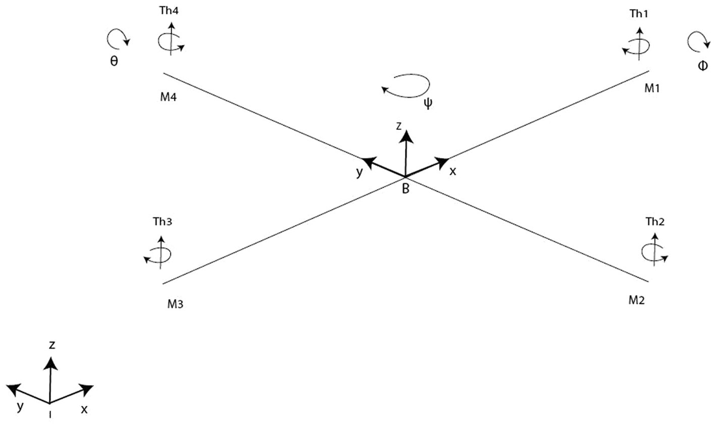
Figure 1. Quadrotor model.
2.2 Flight mechanismsThe motion of quadcopters can be achieved through six distinct maneuvers, which involve a combination of translational and rotational motion as illustrated in Figure 2. There are four inputs on the quadcopter:
• Thrust (z): This input generates a vertical force that enables the quadcopter to hover or move up and down through the air. Increased or decreased speed of all four rotors by a similar amount, greater or lesser than gravitational force, creates the force.
• Roll angle (ϕ): It denotes the quadcopter rotation around the x-axis. In order to create the roll motion, the second rotor’s speed is decreased and the fourth rotor’s speed is increased. These “rolls” move the quadcopter sideways along the y + and y- axis, while maintaining its altitude position.
• Pitch (θ): It corresponds to the quadcopter rotation around the y-axis. By decreasing the first rotor’s speed and increasing the third rotor’s speed, pitch motion can be created. Depending on the quadcopter’s orientation and the position of its nose, the pitch action causes it to tilt upwards or downwards. An upward tilt moves the quadcopter in a backward motion (x-), while a downward tilt moves it forward (x+).
• Yaw (ψ): It refers to the quadcopter rotation around the z-axis. Angular velocities are increased of two opposite rotors while angular velocities of the other two are decreased. Thus, the Yaw motion is generated. Precisely, In both clockwise and counterclockwise rotations, the quadcopter’s front faces the same direction.
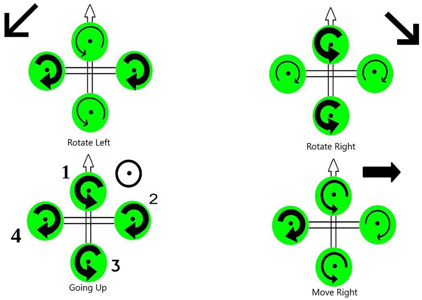
Figure 2. Quadrotor flight mechanisms.
2.3 System coordinatesFirst, let us begin by precising the reference coordinate frame and the coordinate frame of the vehicle body, in order to construct the quadrotor’s mathematical model. Let us denote by B = [Bx, By, Bz]T the body-fixed frame (BFF) and (EFF) E = [Ex, Ey, Ez]T the ground fixed reference coordinate frame also called inertial frame. The center of the BFF origin is aligned with the center of mass of the quadcopter, and its origin is connected to the body of the vehicle.
In the 3-dimensional Euclidean space, we denote B = (x,y,z)T. The coordinate vector IB→ describes the distance between the Inertia frame and the body frame. The three Euler angles ?, ? and ? (so called: roll, pitch, and yaw) describing the quadrotor orientation are represented by the vector Γ = [?,?]?.
The vehicle body frame BFF is considered the base for reference frame analysis. To catch the 3D space’s movements and create our mathematical references, Equations 1–5 are considered:
RBIzψ=cosψ−sinψ0sinψcosψ0001 (1) RBIxϕ=1000cosϕ−sinϕ0sinϕcosϕ (2) RBIyθ=cosθ0sinθ010−sinθ0cosθ (3)- Body frame rotated in ?+:
- Body frame rotated in ? +:
- Body frame rotated in ? +:
The movement from one frame to another in this case is defined by Equation 4:
RBIψθϕ=RBIzψRBIyθRBIxϕ (4)The rotational matrix is then derived as
RBI=cosψcosθsinθsinϕcosψ−cosθsinψsinθcosϕcosψ+sinϕsinψsinψcosθsinθsinϕsinψ+cosϕcosψsinθcosϕsinψ−sinϕcosψ−sinθsinϕcosθcosϕcosθ (5) 2.4 Actuator dynamicsThe actuator dynamic refers to the correlation between the voltage applied to the actuator, which serves as the real control input, and the speed of the rotor. Designers are particularly interested in the speed of the actuator’s response, as it plays a crucial role in the performance of the system. Based on Kirchhoff laws and the law of rotation, we derive the following simplified actuator dynamic model described by Equation 6:
dwidt=−1τwi+Kwτui,∀i=1,..,4 (6) where ? and Kw denotes the delay and gain coefficient, respectively (Bouabdallah et al., 2004). Furthermore, dwidt and ui represent the speed and the input voltage of actuator ?, =1,..,4 . Actuator delay assumes a critical role, especially in cases where the attitude control loop is functioning at a low frequency. 2.5 KinematicsLet us move on to the kinematics side of the conducted study. Herein, the rigid “+” symmetric quadrotor is shown in Figure 1 with four rotors producing (Th1, Th2, Th3, Th4) forces. Quadrotor structure center of mass and origin of body coordinate system are the same. The center of gravity of the system coincides with the origin of the body-fixed frame (BFF). It is assumed that propellers are rigid and that thrust and drag are proportional to the square of the propeller’s rotational speed. The difference between the body rates p, q, r in BFF and the angle rates expressed in EFF should be calculated following Equations 7, 8.
pqr=10−sinθ0cosθsinϕcosθ0−sinθcosϕcosθϕ˙θ˙ψ˙ (7)Where vand Γ˙ represent the angular velocity vectors in both frames the B-frame and E-frame, respectively. Furthermore, the inverse of the matrix M is expressed in Equation 9 as
M−1=1tanθsinϕtanθcosϕ0cosϕ−sinϕ0sinϕcosθcosϕcosθ (9)During position control, the quadrotor’s body must be compensated for rotation. Compensation is obtained by transposing the rotation matrix.
2.5.1 Translation dynamicsBased on the works of Barzegar and Lee (2022) and Quan (2017), the system under study was subjected to the following forces:
The vehicle’s total weight:
The rotors’ generated thrust:
Fth=RBI∑i=14Thi=b∑i=14ωi2sinϕsinψ+sinθcosψcosϕ−sinϕcosψ+sinψcosϕsinθcosθcosϕ (11)The drag force and air friction:
Fdr=CdB˙=−Cdx000Cdy000Cdzx˙y˙z˙=Cdxx˙Cdyy˙Cdzz˙ (12) F=mB¨=P+Fth+Fdr (13)The mass of the quadrotor is represented by m and the acceleration due to gravity is represented by g in Equation 10. Equation 11 expresses that the angular velocity and thrust constant of the ith propeller are represented by ωi and b , respectively. Equation 12 contains the translational drag coefficient matrix denoted by Cd . The position of the center of mass in the coordinates of the Flat Earth, as given in Equation 10, is a vector of the dimensions 3 times 1. Then, the total force is expressed by Equation 13. The equation of motion describing the translational motion of the quadcopter is expressed using Newton’s second law and reads are Equations 14–16:
x¨=1mb∑i=14ωi2sinϕsinψ+cosϕsinθcosψ−Cdxx˙ (14) y¨=1mb∑i=14ωi2−sinϕcosψ+sinψcosϕsinθ−Cdyy˙ (15) z¨=1mb∑i=14ωi2cosθcosϕ−Cdzz˙−mg (16) 2.5.2 Rotation dynamicsThe motion of a quadrotor is clearly attributed to an array of forces and moments resulting from various physical phenomena. A quadrotor experiences torques in roll, pitch, and yaw, as well as aerodynamic friction torque and gyroscopic effects caused by the propellers. To calculate angular acceleration on the body frame, the second law of Newton for rotational motion must be applied, and the Coriolis effect should be taken into account. We can consider for this model the torques detailed in Table 1.
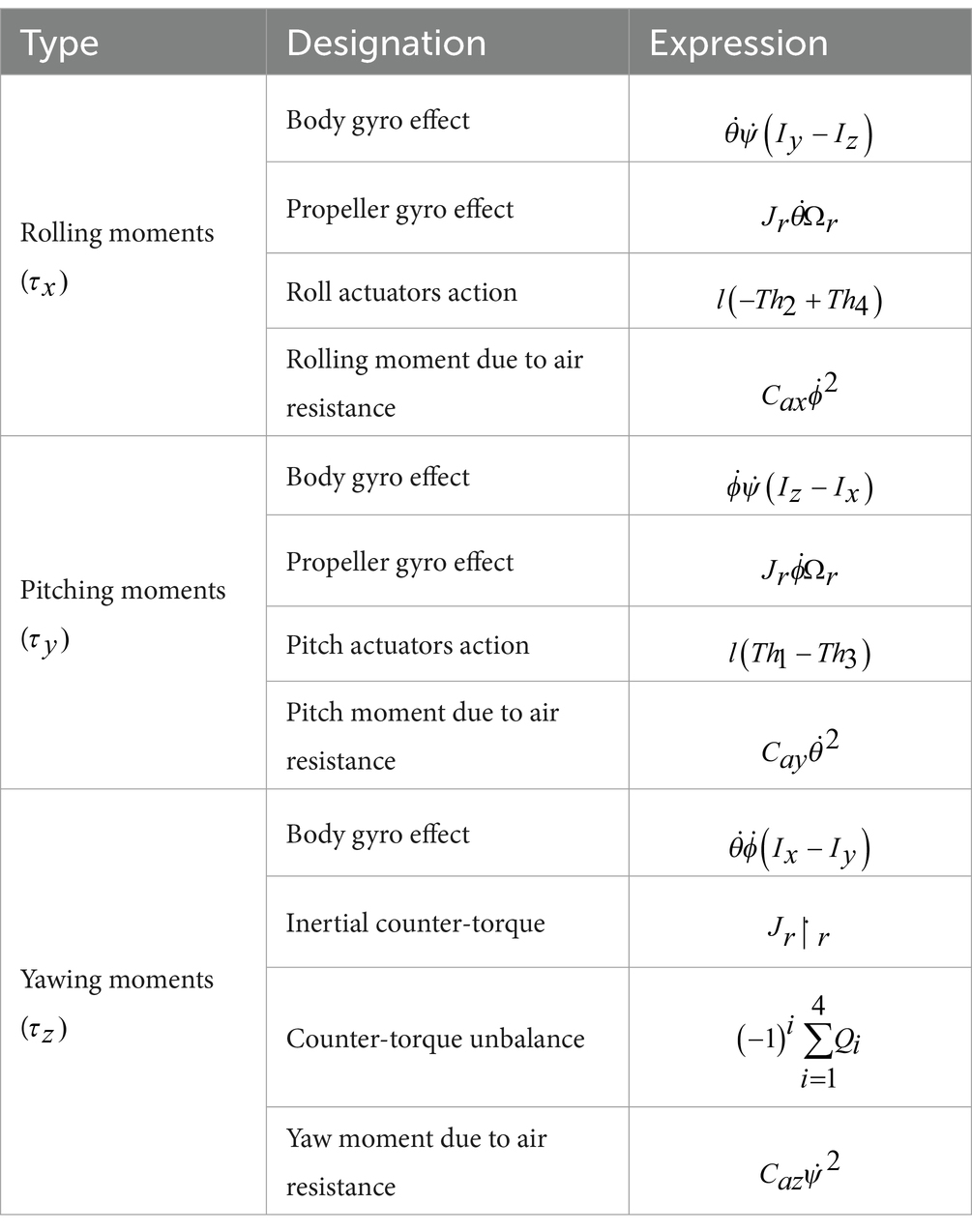
Table 1. Torques details.
Accordingly, the torques can be derived as follows:
τx=0−l0∧00Th2+0l0∧00Th4=lbω42−ω2200 (17) τy=l00∧00Th1+−l00∧00Th3=0lbω32−ω120 (18) τz=00d∑i=14ωi2 (19) τa=Caψ˙2ϕ˙2θ˙2=Cazψ˙2Caxϕ˙2Cayθ˙2 (20) τgp=JrΩr0θ˙−ϕ˙ (21)Equations 17–21 denote that the parameter l indicates the distance of the motor axis from the center of gravity of the quadcopter, while d represents the drag coefficient. Equation 20 depicts Ca as the 3×3 matrix of aerodynamic friction coefficients. In Equation 21, Jr and Ωr represent the rotor’s inertia and rotation velocity, respectively. The rotational motion of the quadrotor is governed by the equations of motion, expressed by Equations 22–24, obtained by using Euler’s rotation equations. In Equations 22–24, moments of inertia along x , y and z directions are represented by Ix , Iy and Iz respectively:
ϕ¨=1Ix−Caxϕ˙2−JrΩrθ˙−Iz−Iyθ˙ψ˙+lbω42−ω22 (22) θ¨=1Iy−Cayθ˙2−JrΩrϕ˙−Ix−Izϕ˙ψ˙+lbω32−ω12 (23) ψ¨=1Iz−Cayθ˙2−JrΩrϕ˙−Ix−Izϕ˙ψ˙+∑i=14−1i+1ωi2 (24) 2.5.3 Mathematical modelConsidering both the translational and rotational dynamics, the entire dynamic model of the quadcopter is expressed as follows:
x¨=1muzux−Cdxx˙ (25) y¨=1muzuy−Cdyy˙ (26) z¨=1muzcosθcosϕ−Cdzz˙−mg (27) ϕ¨=1Ix−Caxϕ˙2−JrΩrθ˙−Iz−Iyθ˙ψ˙+uϕ (28) θ¨=1Iy−Cayθ˙2−JrΩrϕ˙−Ix−Izϕ˙ψ˙+uθ (29) ψ¨=1Iz−Cayθ˙2−JrΩrϕ˙−Ix−Izϕ˙ψ˙+uψ (30) where u=uxuyuzuϕuθuψ is a vector expressed by Equations 31–33 with d as the drag coefficient: ux=sinϕsinψ+cosϕsinθcosψ (31) uy=−sinϕcosψ+sinψcosϕsinθ (32) uzuϕuθuψ=bbbb0−lb0lb−lb0lb0d−dd−dω12ω22ω32ω42 (33)Equations 25–30 exhibit the complete nonlinear model of a quadrotor, revealing its complex dynamics. The strong nonlinearity, including inter-state multiplication, intensive variable coupling, and the presence of multivariable features, poses challenges in designing controllers, while simultaneously eliciting significant researchers’ attention.
2.5.4 Simplified systemThe purpose of the mathematical model is to facilitate the construction of a control system. Nevertheless, if the mathematical model is overly sophisticated, the design of the control system will also be complex. A state space model could be adapted for the control system X˙=fXU where X and U are the state and input vectors, respectively. The state vector X reads as:
X=x,y,z,x˙,y˙,z,̇ϕ,θ,ψ,ϕ˙,θ˙,ψ˙ (34)Let us begin by assuming that
{x1=xx2=yx3=zx4=x˙=x˙1x5=y˙=x˙2x6=z˙=x˙3x7=ϕx8=θx9=ψx10=ϕ˙=x˙7x11=θ˙=x˙8x12=ψ˙=x˙9 (35)Then, Equations 25–40 leads to
X˙=x4x5x61muzux−Cdxx˙1muzuy−Cdyy˙1muzcosθcosϕ−Cdzz˙−mgx10x11x1211x−Caxϕ˙2−JrΩrθ˙−Iz−Iyθ˙ψ˙+uϕ11y−Cayθ˙2−JrΩrϕ˙−Ix−Izϕ˙ψ˙+uθ11z−Cayθ˙2−JrΩrϕ˙−Ix−Izϕ˙ψ˙+uψ (36)Equation 36 indicates that rotational movements are functionally independent of translational movements and are entirely actuated. However, translational movements are under actuated and highly dependent on rotational movements. A control loop structure comprising both an inner and outer loop has been devised. The inner control loop guarantees asymptotic tracking of the desired attitude and altitude, ensuring precise control. On the other hand, the outer loop is responsible for conducting navigation, overseeing the path planning and overall trajectory of the system.
It is possible to make certain simplifying assumptions for the previous model, without compromising the precision of the motion behavior to a significant extent. To minimize the complexity of calculations, it is presumed that the quadrotor is near a hovering position, with very little changes in angles and angular acceleration contribution. Resulting in a null attitude angular rates (
Comments (0)