
記住我

Cervical pedicle screws (CPS) have been used for the stabilization of the lower cervical spine since they were first described by Abumi et al[1] in 1994, albeit their use has been limited because of the risk of complications. Clinical studies have demonstrated that screw misplacement leads to complications[2,3] and have emphasized the benefits of CPS owing to its superior biomechanical strength.[4] Consequently, subaxial CPS has become indispensable for posterior cervical spine fixation and stabilization of subaxial cervical instabilities caused by trauma, osteoporosis, or tumor disorders.[3] Despite the consideration of various insertion angles for posterior subaxial CPS, no consensus has been reached on the ideal medial angle. The study aimed to statistically and qualitatively investigate the subaxial cervical pedicle and its relationship with nearby neurovascular networks to establish the best entry point and trajectory for posterior subaxial CPS. This research has the potential to be translated into clinical practice through the lens of translational medicine, bridging the gap between basic research and its practical application for improved healthcare outcomes.[5]
2. Methods 2.1. Population researchAmong the 565 cervical spine computed tomography (CT) scans performed at our institution between September 2019 and September 2021, 375 were excluded for not meeting the inclusion criteria, which required a normal cervical spine. Sampling was performed using a random number table. After coding 190 cervical spine CT scans with normal reports, the SPSS software randomly generated 190 numbers that were then sorted. From the initial pool of cervical CT spine scans, consisting of 190 scans with normal results, a random selection of 42 participants was made for the study. The group comprised 21 males and 21 females, with ages ranging from 19 to 71 years (39.1 ± 15.2 years). Moreover, the patients underwent CT scans using a 0.625-mm slice thickness for the cervical spine due to neck pain (Philips Brilliance 64 CT, Philips Medical Systems, Amsterdam, Netherlands). The exclusion criteria included any patients with evidence of cervical spine injury; medical pathology of the cervical spine (endocrinopathies or other disorders affecting bone metabolism); surgical pathology of the cervical spine; infectious, neoplastic, traumatic, or congenital complications. Axial images along with coronal and sagittal reconstructions were included for each CT scan. The study was approved by the Medical Ethics Committee of the Ningbo No.6 Hospital (approval number:2022-154 (L)).
2.2. CT findings assessedVolumetric imaging data captured in digital imaging and communications in medical format were imported using Mimics 20.0. (Materialize, Leuven, Belgium). Three-dimensional cephalometric analysis was performed using the Mimics software and CT data. The auto computer-aided design software was used to measure the width of the subaxial cervical pedicle (width of accuracy: 0.01 mm). Furthermore, for each patient axial, coronal, and sagittal CT reconstruction images were analyzed. To better align the morphology of the subaxial cervical vertebral between the image sets, the coordinate origin (point O) was assumed to coincide with the spinal canal endpoint (Fig. 1A). The X-axis is parallel to a line connecting the lowest point of the outer edge of each side of the inferior articulating process, the Y-axis is perpendicular to the X-axis and passes through point O and the lowest point of the atlas posterior arch, and the median sagittal plane is perpendicular to the X-axis (Fig. 1B). During the measurement procedure, the image was subjected to an enlargement exceeding a tripling factor. Each measurement indicator was meticulously replicated 3 times, and all indicators were independently assessed by 3 proficient spine surgeons.
 Figure 1.:
 (A) To better align the subaxial cervical vertebral morphology between picture sets, the coordinate origin (point O) was assumed to coincide with the endpoint of the spinal canal. The X-axis occupies the coronal plane and is parallel to a line connecting the lowest point of the inferior articulating process on each side. The Y-axis is perpendicular to the X-axis and passes through point O and the lowest point of the cervical vertebral body, and the median sagittal plane is perpendicular to the X-axis. (B) the transverse plane of the atlas is made up of the X- and Y-axis whereas the sagittal plane is made up of the Y- and Z-axis.
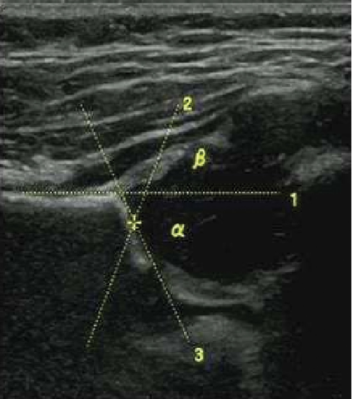
2.3. Measurements of morphologyThe same cephalad degree was used to measure the subaxial cervical pedicle width. The following subaxial cervical pedicle characteristics were used to evaluate the appropriate medial angles: pedicle width (PW) (Fig. 2A) and subaxial cervical PW of 30°, 35°, 40°, 45°, 50°, 55°, and 60° medial angulation (Fig. 2B). Appropriate medial angles for the posterior subaxial CPS were determined by measuring the PW of the subaxial cervical pedicle. The pedicle width and medial angle of C3–7 pedicle screw mean values in the left, right, and bilateral scatter plots are illustrated in Figure 3. In Male and female patients, the total PW and medial angle of the C3–7 CPS are displayed in a scatter plot (Fig. 4).
 Figure 2.:
 (A) The C3–7 cervical pedicle screw (CPS) medial angulation ranged from 30° to 60°. (B) The pedicle width (PW) of the C3–7 CPS was assessed between 30° and 60°, with PW values changing as the medial angulation rotated. The measurements were performed in the transverse plane of the median sagittal plane.
 Figure 3.:
 Pedicle width (PW) and medial angle of C3–7 cervical pedicle screw (CPS) mean values in the left, right, and bilateral scatter plots. As the medial angle increased from 30° to 60°, the interval variability in PW values for the C3–7 CPS increased and subsequently decreased.
 Figure 4.:
 Male, female, and overall mean values of pedicle width (PW) and medial angle of C3–7 cervical pedicle screw (CPS) in a scatter plot. With an increase in the medial angle from 30° to 60°, the interval changes in PW values for the C3–7 CPS first increased and subsequently decreased.
2.4. Statistical analysisThe SPSS software package (version 21; IBM SPSS Inc., Chicago, IL) was used for statistical analysis. Values are expressed as ranges, means, and standard deviations (SD) if appropriate. At a 95% level of significance, Student t test was used to analyze the statistical significance of the morphometric data. The level of significance for all statistical analyses was set at P < .05. Paired t-tests were conducted to examine whether there were any statistically significant differences in the measurements collected from the left and right sides. To evaluate the differences between the 2 sexes, a 2-sample t test with similar variance was performed. To examine PW differences among different medial angles, analysis of variance (ANOVA) with a randomized block design was used, followed by a posthoc Student Newman Keuls-quantitative test for individual comparisons.
3. ResultsThe right and left subaxial cervical pedicles were investigated using CT scans of 42 patients. The average age of the patients was 39.1 years (range, 19–71) and half of the CT scans were performed in males. There were no statistically significant differences between male and female C3–6 pedicles, and no statistically significant differences between right- and left-sided subaxial cervical pedicles for these features; thus, we pooled the left and right results for all statistical analyses (Table 1). As the mean, SD, and range of the C7 PW differed significantly between male and female patients, the mean, SD, and range of the C7 PW by sex are reported in (Table 2). For 30°, 35°, 40°, 45°, 50°, 55°, and 60° medial angulation, the average C3 PW was 5.64, 5.88, 6.05, 6.12, 6.11, 6.02, 5.86, respectively; average C4 PW was 5.44, 5.77, 6.02, 6.17, 6.25, 6.24, 6.14, respectively; average C5 PW was 5.80, 6.14, 6.38, 6.54, 6.60, 6.57, 6.45, respectively; average C6 PW was 6.43, 6.70, 6.89, 6.97, 6.96, 6.86, 6.67, respectively; and average C7 PW was 7.33, 7.36, 7.28, 7.21, 6.95, 6.59, 6.14, respectively. The female and male results in C3–6 PW were not substantially different. Additionally, no significant differences were observed in the right- and left-sided measures for each parameter. Although the differences in C3–6 PW between 45°, 50°, and 55° were not statistically significant, they were significantly larger than those between 30°, 35°, 40°, and 60° (P < .05) (Table 3–6). The C7 PW disparities at 30°, 35°, 40°, and 45° were not significantly different; however, they were significantly larger than the discrepancies between 50°, 55°, and 60° (P < .05) (Table 7). Different subsets were statistically significant, and the same subset demonstrated no statistical significance (P <. 05). As the lowest and greatest medial angulations for the largest PW differed, no universally acceptable values were provided. Left, right, and bilateral scatter plots of the PW and medial angle of the C3–7 CPS mean values are displayed in Figure 3. Male, female, and general mean PW and medial angle of the C3–7 CPS are illustrated in a scatter plot (Fig. 4). Based on an observational examination of the positions of all cervical 3-dimensional models and screws, the proposed entry point for C3–7 CPS was under the junction of the lateral and lower borders of the superior articular process joint surface (Fig. 5A). The sagittal angle for C3–7 CPS was perpendicular to the posterior surface (Fig. 5B), and the medial angle for C3–7 was perpendicular to the cervical spine lamina (slightly >90°) (Fig. 5C).
Table 1 - The value of PW for each degree of C3-6 pedicle screw medial angle (mean ± SD). 30° 35° 40° 45° 50° 55° 60° C3 5.64 ± 0.83 5.88 ± 0.84 6.05 ± 0.84 6.12 ± 0.85 6.11 ± 0.87 6.02 ± 0.88 5.86 ± 0.91 3.58~7.66 3.75~7.98 3.99~8.24 4.05~8.41 4.04~8.53 3.92~8.49 3.71~8.40 C4 5.44 ± 0.0.76 5.77 ± 0.77 6.02 ± 0.79 6.17 ± 0.81 6.25 ± 0.83 6.24 ± 0.85 6.14 ± 0.86 2.74~6.93 3.07~7.30 3.31~7.58 3.47~7.80 3.56~7.93 3.63~7.96 3.62~7.86 C5 5.91 ± 0.81 6.24 ± 0.81 6.49 ± 0.84 6.65 ± 0.85 6.72 ± 0.86 6.69 ± 0.88 6.57 ± 0.91 4.39~8.54 4.65~8.97 4.79~9.36 4.84~9.65 4.84~9.88 4.73~10.04 4.51~10.09 C6 6.54 ± 0.93 6.82 ± 0.91 7.01 ± 0.91 7.09 ± 0.91 7.08 ± 0.93 6.98 ± 0.96 6.78 ± 0.99 4.54~10.48 4.83~10.83 5.13~11.08 5.32~11.2 5.19~11.23 4.92~11.10 4.55~10.85 C7 7.85 ± 1.32 7.88 ± 1.33 7.79 ± 1.35 7.62 ± 1.38 7.34 ± 1.41 6.97 ± 1.43 6.51 ± 1.46 5.55~12.52 5.60~12.79 5.55~12.96 5.38~13.08 5.11~13.08 4.74~12.97 4.28~12.07Measured in the transverse plane. Data are presented as range and mean ± standard deviation (SD).
PW = pedicle width.
Measured in the transverse plane. Data are presented as range and mean ± standard deviation (SD).
PW = pedicle width.
†Derived with post hoc SNK (Student-Newman-Keuls)-q test for individual comparisons.
‡Different subsets have statistical significance, and the same subset has no statistical significance (P < .05).
†Derived with post hoc SNK (Student-Newman-Keuls)-q test for individual comparisons.
‡Different subsets have statistical significance, and the same subset has no statistical significance (P < .05).
†Derived with post hoc SNK (Student-Newman-Keuls)-q test for individual comparisons.
‡Different subsets have statistical significance, and the same subset has no statistical significance (P < .05).
†Derived with post hoc SNK (Student-Newman-Keuls)-q test for individual comparisons.
‡Different subsets have statistical significance, and the same subset has no statistical significance (P < .05).
†Derived with post hoc SNK (Student-Newman-Keuls)-q test for individual comparisons.
‡Different subsets have statistical significance, and the same subset has no statistical significance (P < .05).
 Figure 5.:
 (A) for C3–7 levels, the proposed entry point is under the junction of the lateral and lower borders of the superior articular process joint surface. (B) Subaxial cervical pedicle screws have a sagittal angle that approaches perpendicular to the lateral mass posterior surface. (C) a medial angle that approaches perpendicular to the cervical spine lamina (slightly >90°).
4. Discussion 4.1. Advancements and considerations in subaxial CPS for lower cervical spine stability: Exploring safety and entry point guidelinesOwing to advancements in fixation methods for lower cervical spine stability and the introduction of several systems, including subaxial CPS, intraoperative reduction of lower cervical spine deformities has become a viable option in some cases.[1] Despite its excellent biomechanical qualities, it is not commonly used due to the unresolved and inherent threat of screw perforation, which can cause neurovascular injuries.[2] Posterior instrumentation of the cervical spine with CPS has long been considered dangerous owing to its small margin of error.[1,2] The reported CPS malposition rates using the freehand technique vary from 6.7% to 26.7%.[2,6] Even the most seasoned surgeons are concerned about the possibility of neurovascular consequences, such as nerve root and vertebral artery injury.[1] Differences in the anatomy of the cervical pedicles and the path of the vertebral arteries aggravate the condition.[2] Moreover, CPS is considered to be the most stable instrument for cervical spine repair.[4] Therefore, the use of CPS for deformity surgery, osteoporotic bone, and stabilization of unstable segments, such as those caused by trauma, tumors, or spondyloarthritis, is advantageous.[4] Concerning the entry point for subaxial cervical screws, Burcev et al[7] demonstrated that standardizing the methods of CPS entry point coordinates to 2 mm from the lateral and 2 mm from the upper edge of the posterior surface of the lateral mass is possible. Lee et al[8] used the superior ridge of the lateral mass and the center of the lateral mass as landmarks to obtain an entry from 2.0–2.4 mm medial and 0–0.9 mm inferior to the lateral notch. C3–7 levels, according to Tan et al[9] the entry point should be slightly medial to the lateral vertebral notches and slightly inferior to the inferior articular process edge of the neighboring cranial vertebra. According to Sakamoto et al,[10] the entrance point should be situated as far laterally as possible on the posterior surface of a lateral mass. Although the entrance point of each vertebra should be altered according to the transverse angles of the pedicles, certain guidelines should be followed. In the study, the proposed entry point for C3–7 levels was below the junction of the lateral and lower borders of the superior articular process joint. The mean sagittal angles of the CPS were equal at C4–C7, almost parallel to the corresponding upper endplate, and oriented 7° upward at the axis of the C3 pedicle, according to Lee et al[8] Chazono et al[11] support the aforementioned view. According to Burcev et al, the sagittal plane trajectory should be perpendicular to the posterior surface of the lateral mass.[7] The C3–7 CPS were parallel to the upper endplate of the vertebral body in the sagittal plane, and we believe that the sagittal angle of the subaxial CPS was perpendicular to the posterior surface of the lateral mass. According to Karaikovic et al,[12
留言 (0)